← Home · Ground improvement

Vibrocompaction Design for Loose Sandy Soils in Swords

Together, we solve the challenges of tomorrow.

LEARN MORE →

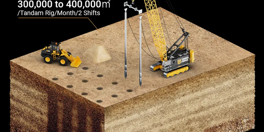
The depth vibrator itself is a steel lance, roughly 3–4 metres long, with eccentric weights spinning at 1800 rpm inside a sealed casing. In Swords, where the glacial sands beneath the Broadmeadow valley can extend 15 metres deep, we typically mobilise an electric-driven V23 or V32 unit suspended from a crawler crane. The vibrator is lowered under its own weight, fluidised by water jets at the tip. Compaction starts from the bottom, lifting in 0.5-metre increments. We measure amperage continuously because in the loose alluvial deposits near the Ward River, the power draw tells you more about densification than any surface observation. Unlike dynamic compaction, there is no crater and no flying debris—just a clean, systematic grid of probe points that densifies the soil mass from the inside out.

In Swords’ glacial sands, amperage logs from the vibrator give a real-time signature of densification—no need to wait for lab results to confirm the improvement.

Methodology and scope

A few years back we worked on a three-storey apartment block off the Rathbeale Road. The site investigation showed a 9-metre layer of loose silty sand with SPT N-values below 6. The developer needed a bearing pressure of 200 kPa for conventional footings, but the untreated ground would have settled unevenly. Our team laid out a triangular grid at 2.1-metre spacing. We ran the vibrator to 10 metres, pulling a vacuum in the annulus to prevent sand from collapsing back into the hole. After compaction, we ran a series of CPT tests to verify the improvement—cone resistance jumped from 4 MPa to over 14 MPa across the entire pad footprint. The structural engineer was then able to eliminate the piled foundation originally specified, saving the client considerable time and mobilisation costs.
Vibrocompaction Design for Loose Sandy Soils in Swords
Technical reference image — Swords

Local considerations

Swords’ expansion since the 1970s has pushed development onto the glacial outwash plains east of the village core. Much of this land was farmed for centuries and the top two metres often contain soft silty clays and buried organic lenses from old drainage ditches. The real risk in vibrocompaction here is not the sand itself but the interbedded soft layers that do not densify. If a vibrator passes through a peat pocket without the operator noticing, the column of compacted sand below that depth is compromised. We cross-check every probe log against the ground investigation, and in transition zones we slow the withdrawal rate to 0.3 metres per minute. This attention to detail prevents differential settlement that could crack blockwork long after handover.

Need a geotechnical assessment?

Reply within 24h.

Email: contact@geotechnical-engineering.co

Explanatory video

Technical parameters

ParameterTypical value
Typical vibrator power130–180 kW (electric)
Frequency range30–50 Hz
Probe spacing (triangular grid)1.8–3.0 m
Maximum treatment depthUp to 25 m
Target relative density (Dr)70–85 %
Applicable soil typeClean sands, silty sands (fines < 15 %)
Verification methodCPT before/after, SPT, PMT
Design standardEN 1997-1 (Eurocode 7)

Associated technical services

01

Vibrocompaction Grid Design & Specification

We prepare detailed probe layouts with target depths, amperage acceptance criteria, and withdrawal rate limits. Every grid is tailored to the specific stratigraphy encountered in the site investigation boreholes.

02

Post-Treatment CPT Verification in Swords

Within seven days of compaction, we return with a CPT rig to confirm cone resistance and sleeve friction. Reports include before-and-after comparisons with Eurocode 7 design parameters for the improved ground.

Applicable standards

IS EN 1997-1:2005 (Eurocode 7 – Geotechnical design), IS EN 1998-5:2005 (Eurocode 8 – Foundations, retaining structures), ICE Specification for Ground Treatment (UK practice adapted for Ireland), ASTM D6066-11 (Practice for determining normalised penetration resistance for liquefaction assessment)

Frequently asked questions

What soil types in Swords are suitable for vibrocompaction?

The technique works best on clean sands and silty sands with fines content below 15–20 %. Much of Swords sits on glacial sands and gravels that respond well. However, zones with soft silty clay lenses or buried organic material need careful assessment—vibratory energy does not densify cohesive soils. We always cross-reference borehole logs to identify any interbedded layers that could limit the treatment effectiveness.

How do you verify that the ground improvement has worked?

Our primary verification tool is the CPT, run at selected locations within the treatment grid. We compare cone resistance (qc) and friction ratio before and after compaction. For a typical Swords project, we aim for a post-treatment qc increase of at least 2–3 times the pre-treatment value. Additional checks may include SPTs or pressuremeter tests if the design requires deformation modulus values.

How close to existing buildings can vibrocompaction be carried out?

We normally maintain a minimum stand-off distance of 3–5 metres from existing structures, depending on their condition and foundation type. The vibrations attenuate quickly in sand, but for sensitive or heritage buildings in Swords’ older village centre, we monitor peak particle velocity with geophones and adjust the vibrator frequency if needed.

What is the typical cost range for a vibrocompaction design and verification package?

For a medium-sized residential or commercial site in Swords, the combined design, supervision, and post-treatment CPT verification package typically falls between €1,280 and €4,820. The spread reflects site size, depth of treatment, and the number of verification locations required. We provide a fixed-price proposal after reviewing the ground investigation data.

Can vibrocompaction reduce the risk of liquefaction in Swords?

Yes—this is one of the key drivers for using the technique in areas underlain by loose saturated sands. By raising the relative density above 70–75 %, the sand gains enough confinement to resist pore pressure build-up during seismic shaking. We evaluate liquefaction potential using CPT-based methods (Youd & Idriss) and design the grid to achieve the target factor of safety required by Eurocode 8.

Location and service area

We serve projects across Swords and its metropolitan area. More info.

View larger map